MECHANICAL DESIGN
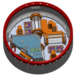
The CAPILUX experiment consists of three major subsystems:
1. Test chambers- In total there are 4 test chambers, where different geometric shapes and test liquid are placed inside them
2. Observation system- It’s responsible for capturing the experiment date. Our experiment data consists of capillary flow due to capillary action and it’s observed by RunCam Split 4 V2 cameras. Each test chamber has dual camera setup for redundancy.
3. Liquid absorption system- To facilitate safety, liquid absorption system is intigrated within the experiment.
The experiment is interfaced inside the 120mm REXUS module using
a bottom bulkhead. The experiment sits just above the REXUS38 rockets service module.
CFD DESIGN
CAPILUX is simulated in ANSYS Fluent (Volume of Fluid model) to predict where the test liquid sits through each phase of flight, with real REXUS 33 flight data driving the analysis. During launch the rocket is spinning, so centrifugal force dominates and pushes the liquid out toward the outer ends of the radially mounted chambers; the simulations confirmed the fluid settles into the intended position with no significant sloshing on the way up. The critical phase is de-spin, where the spin rate is cut to near zero within about a second. That sudden change throws the liquid across to the wrong side of the chamber — the opposite of what the experiment needs, since the fluid should travel through the capillary structures under its own surface tension. To control this, a sloshing baffle was designed and re-simulated, keeping most of the liquid on the correct side through de-spin so the microgravity capillary phase can start cleanly.
THERMAL DESIGN
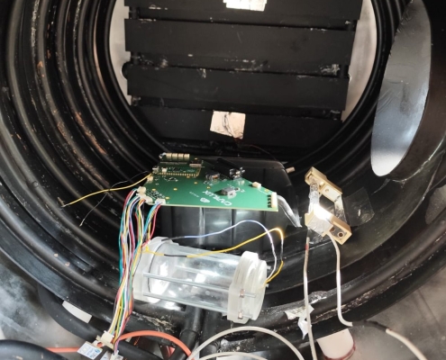
The experiment relies entirely on passive thermal management — no heaters or fans are needed. Heat is generated mainly by the mainboard, the cameras and the LED/pressure PCBs, and in the vacuum of flight it is dissipated through conduction and radiation. Transient thermal analysis is carried out for the cameras and the pressure/LED boards to confirm every component stays within its operating temperature range across the full flight. The worst case assumes no convection for the entire experiment window, leaving only conduction and radiation to manage the load. To better understand the thermal situation of our experiment, vacuum chamber testing is performed.
ELECTRICAL DESIGN
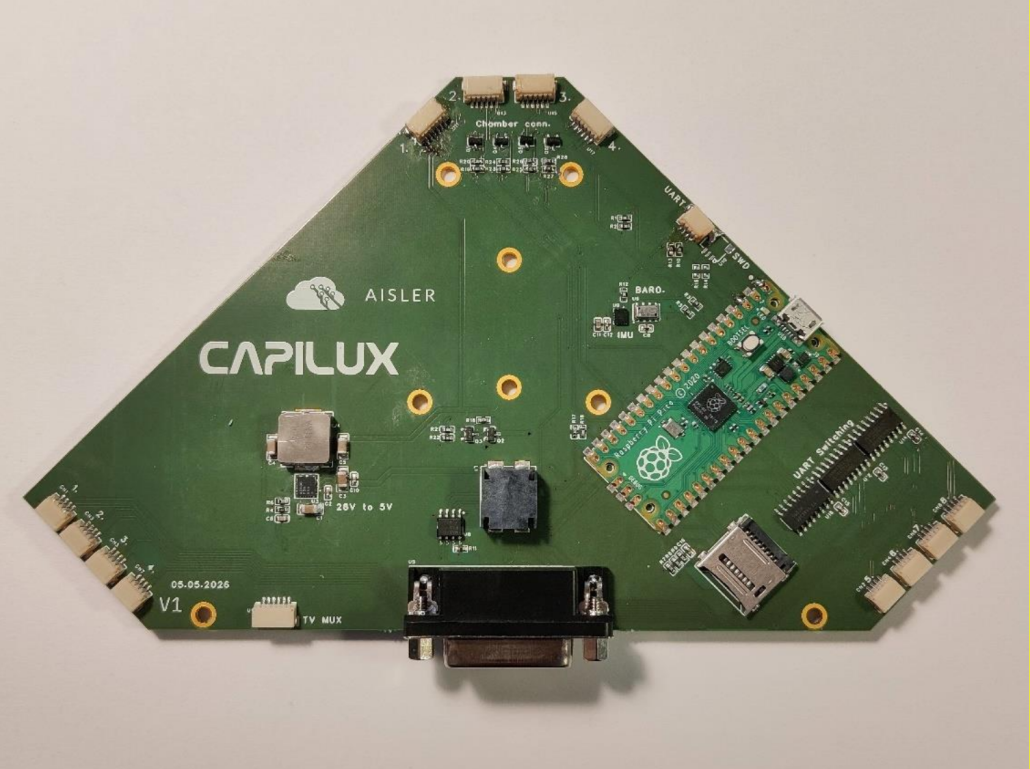
CAPILUX is controlled by a single mainboard mounted to the module bulkhead. It conditions the 28 V REXUS bus down to 5 V and 3.3 V, receives the lift-off and start-of-experiment signals from the rocket, drives the cameras and chamber LEDs, and logs acceleration and environmental data to both onboard flash and an SD card. Eight RunCam Split 4 V2 cameras observe the chambers, each paired with a DVR mounted to the bulkhead for cooling. Pressure and lighting are handled by small PCBs built into the chamber end caps, and a dedicated TV multiplexer board switches all eight camera feeds into a single video downlink for live monitoring before and during flight.
SOFTWARE DESIGN
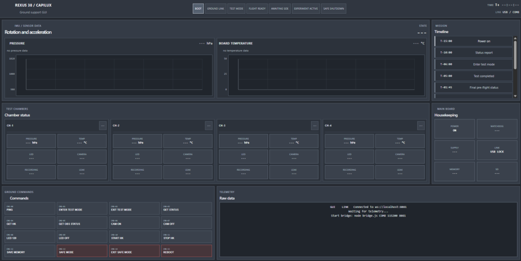
The CAPILUX software is responsible for controlling the experiment before and during flight. It manages the onboard flight computer controlling the cameras and LEDs, collecting sensor data and storing the experiment data. This subsystem is developed to work autonomously during flight, but before launch, the same software allows the team to test cameras, sensors, LEDs, communication and data logging from the ground station. A custom ground station user interface displays telemetry, subsystem status, memory information and housekeeping data downlinked from the onboard flight computer, while also allowing commands being sent during pre-flight checks. The software is built around traceability and data protection, ensuring that recorded experiment data remains usable even if power or communication is interrupted.